RC car
A skid-steer car with four geared motors, printed suspension and an ESP32 receiver that locks onto the first controller it hears. The electronics ran by radio on the bench; the car was never fully assembled.
| Drive | four geared DC motors, skid steering, two motors per driver channel |
| Receiver | ESP32 DevKit, MicroPython, ESP-NOW |
| Motor control | 100 Hz PWM, one PWM and one direction pin per side |
| Power | two 18650 Li-ion cells in series (Samsung INR18650-25R), XT60, rocker switch, voltmeter |
| Suspension | four printed coil-over shocks, steel springs |
| Bottom plate | 220 × 138 mm, drawn in Blender |
| Body | Lancer Evo X mesh by BadKarma™ (CC-BY 4.0), not printed |
| Result | circuit bench-tested by radio, car not fully assembled |
A four-wheel skid-steer car. Its ESP32 receiver takes the raw stick position from my radio controller over ESP-NOW, pairs itself to the first controller it hears and mixes the stick into left and right motor speeds. The motors and wheels are bought. The shocks, the motor cases and a case for every board are my designs, modelled in Blender and printed on my Elegoo Neptune 4; the design also has a 220 × 138 mm bottom plate of my own. The hardware took shape between 12 October and 7 November 2024, and the receiver firmware followed in February 2025.
Power and printed cases, 12 to 24 October 2024
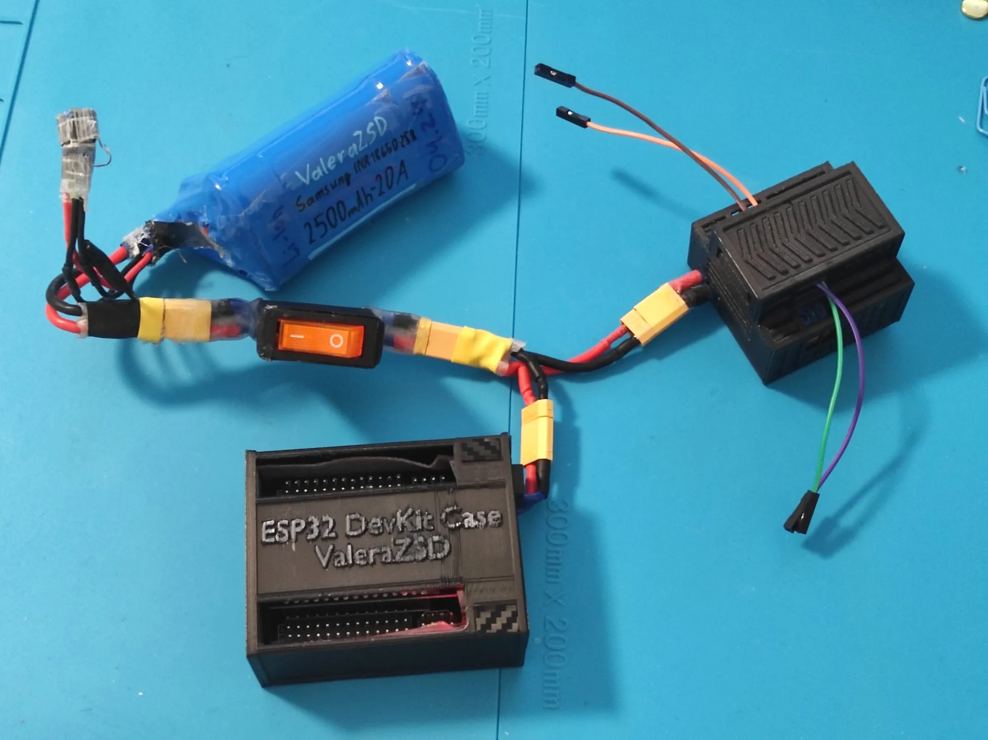
The first bring-up was on 12 October 2024: the ESP32 DevKit and a red motor driver board with a finned heatsink, powered through XT60 connectors and a rocker switch. The battery is two Samsung INR18650-25R cells (2500 mAh, 20 A) that I soldered in series into a pack in April 2024. Between 14 and 17 October every board got a printed case: the ESP32 case with my handle embossed on it, a case for the switch, and a vented two-deck case for the driver. On 24 October I added a small voltmeter in its own case on the front of the driver case; it shows the battery voltage.
Printed shocks, 13 to 20 October 2024
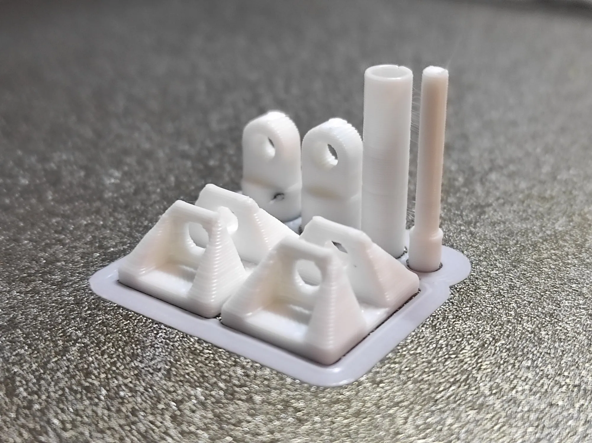
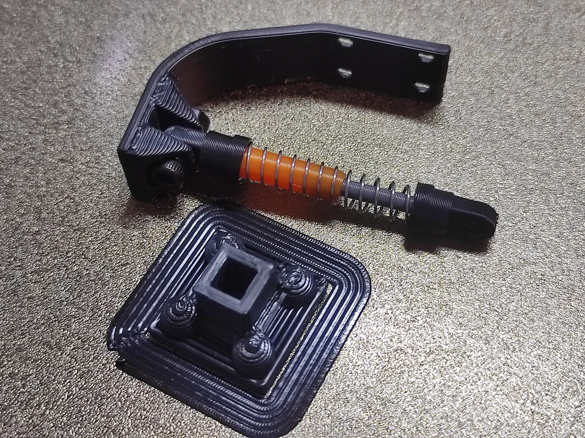
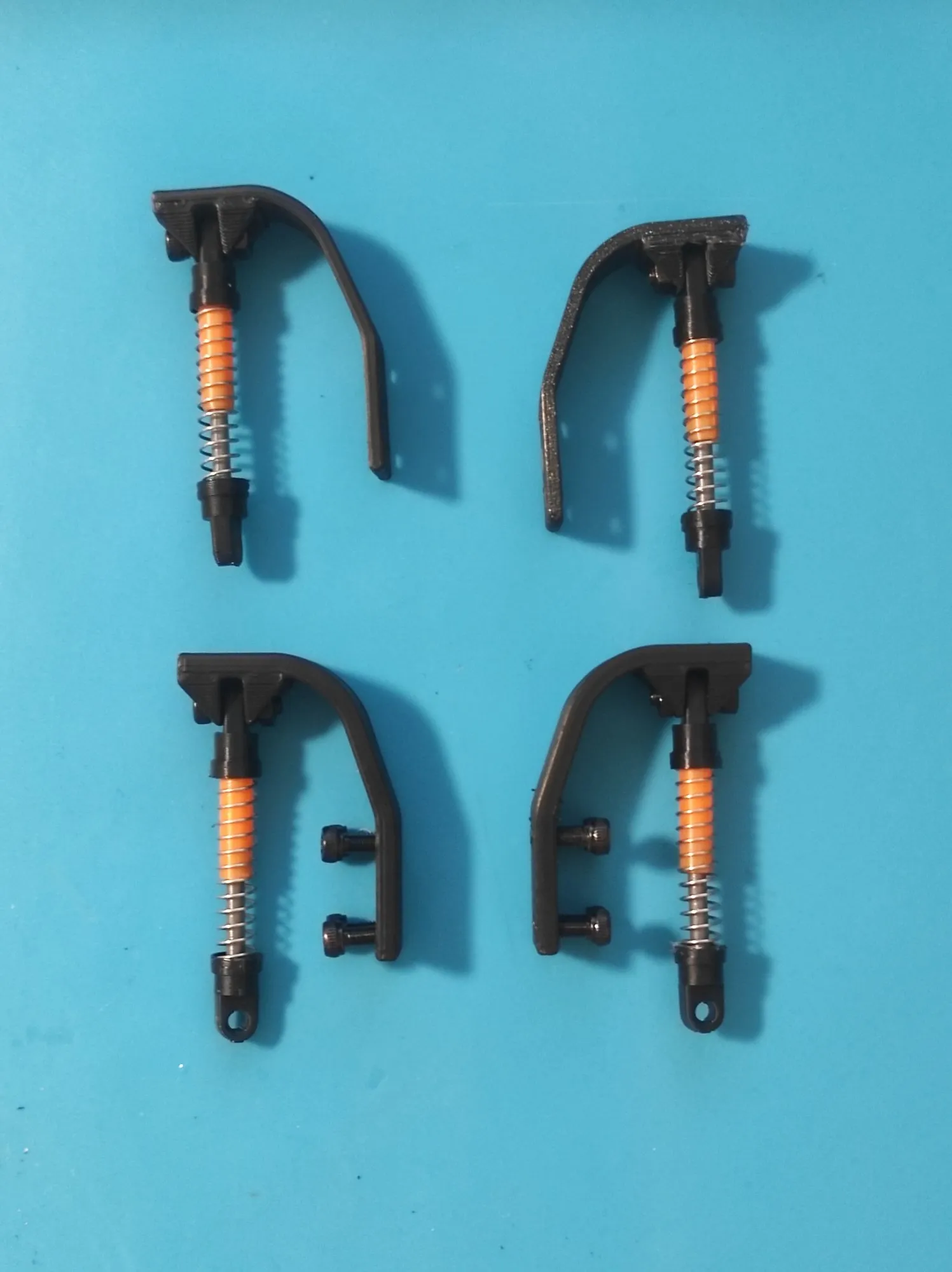
Each shock is a top eye, an orange sleeve, a grey inner rod and a bottom eye, all printed, around a steel spring, with a printed hinge base at the mount. I modelled the first version on 13 October. On 19 October I refined the fit over several small test prints, then printed the final parts in black, orange and grey, along with a curved arm that carries each shock. The first finished shock was on its arm early on 20 October, and all four were assembled that evening.
Four driven corners, October to November 2024
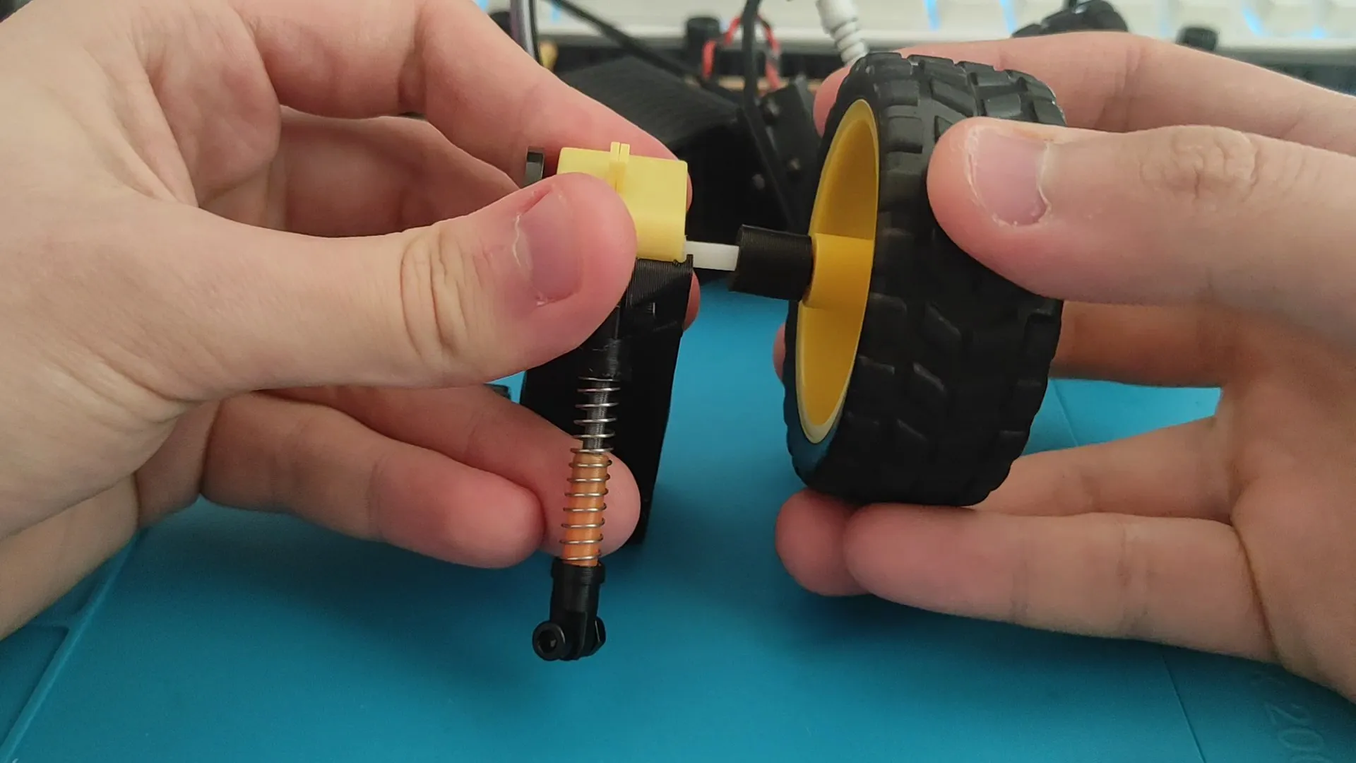
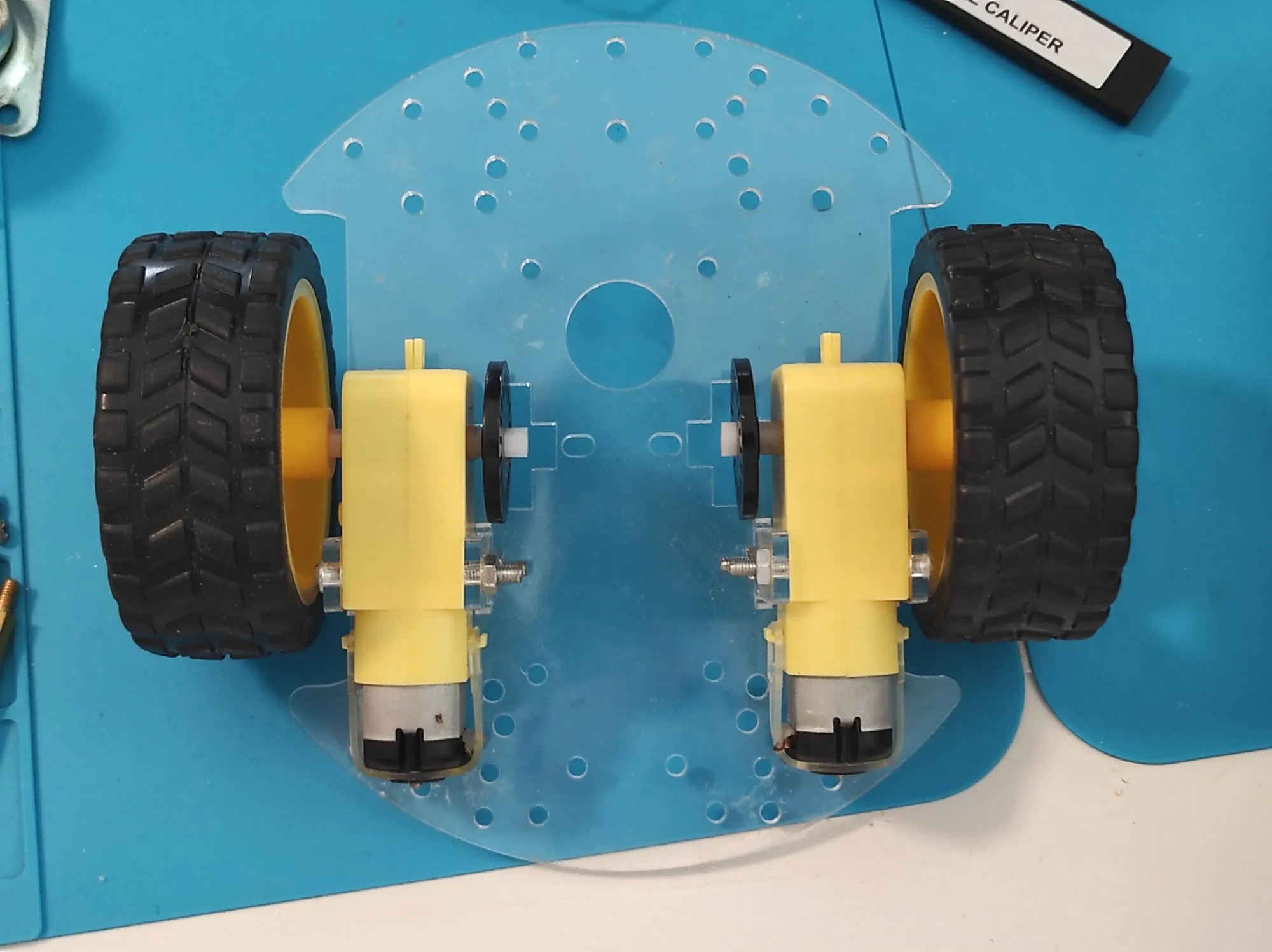
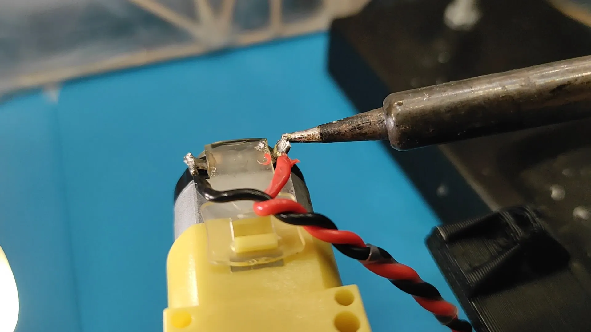
The car started as the common acrylic kit, a round plate with two yellow gear motors. My design has four driven corners instead, each a geared motor in its own printed case. The first test prints of that case are from 17 October, and on 21 October I made twisted lead pairs for the four motors and started soldering them on. The motor case reached its final shape on 1 November, and on 3 November I printed the extenders that sit between the motor shafts and the wheels. The driver has two channels, so the two motors on each side run in parallel.
The body stayed in Blender, October to November 2024
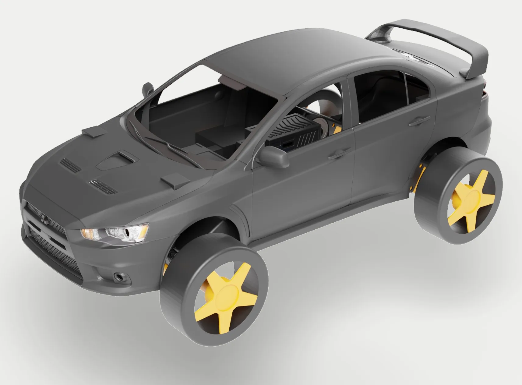
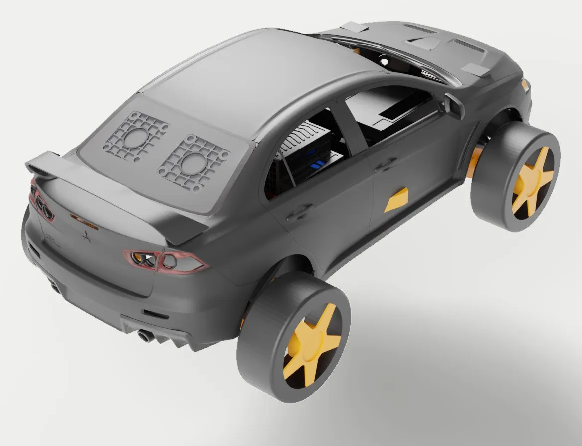
The body is the Mitsubishi Lancer Evo X by BadKarma™ from Sketchfab, under CC-BY 4.0. I scaled it over the chassis in Blender and placed the electronics cases inside the cabin. I replaced the rear window with a grille and mounts for two fans, to keep air moving through the cabin past the motor driver, which gets hot under load; the grille takes its look from the radiator vents on rally cars. The body was never printed.
A receiver that picks its controller, February 2025
I wrote the receiver in MicroPython on 9 February 2025, for the packet that the first, bare-board version of the controller sends: the stick’s x and y and its push switch as JSON. At power-up the car holds both motors at zero duty and waits. The first ESP-NOW packet decides which controller it belongs to: it stores that sender’s MAC address and ignores every other sender from then on.
The car does the mixing, with the widely shared joystick-to-differential function (the Savage Makers Python version). The stick’s angle sets how hard it turns, the larger axis sets the speed, and out come a left and a right value between -1023 and 1023.
Each side has one PWM pin at 100 Hz and one direction pin. Forward is the direction pin low with the speed as duty. Reverse holds the direction pin high and inverts the duty to 1023 minus the speed, so the one PWM pin covers both directions. A boot script holds all four motor pins low at start-up. Pressing the stick is the kill switch: both sides drop to zero duty with their direction pins low, and the control loop ends until a reset.
The open gap is signal loss: if packets stop arriving, the motors hold their last speed, because nothing in the loop times them out.
I ran the whole circuit by radio on the bench: controller, receiver, driver and all four motors, each turning the right way and following the stick’s speed.