Other builds
A 16×16 LED panel running my own fire and bouncing-ball code, a phone-controlled lamp, a 12 V MOSFET dimmer, an RP2040 USB keyboard stick and printed cases.
| Boards | ESP32-C3 SuperMini, Seeed XIAO RP2040, an RP2040 USB board, an Arduino-compatible board, Luckfox Pico Pro/Max |
| LED panel | 16×16 flexible WS2812 matrix (256 LEDs), C++ on Adafruit NeoPixel |
| Lamp | printed cylinder diffuser, ESP32-C3 serving its own control page over Wi-Fi |
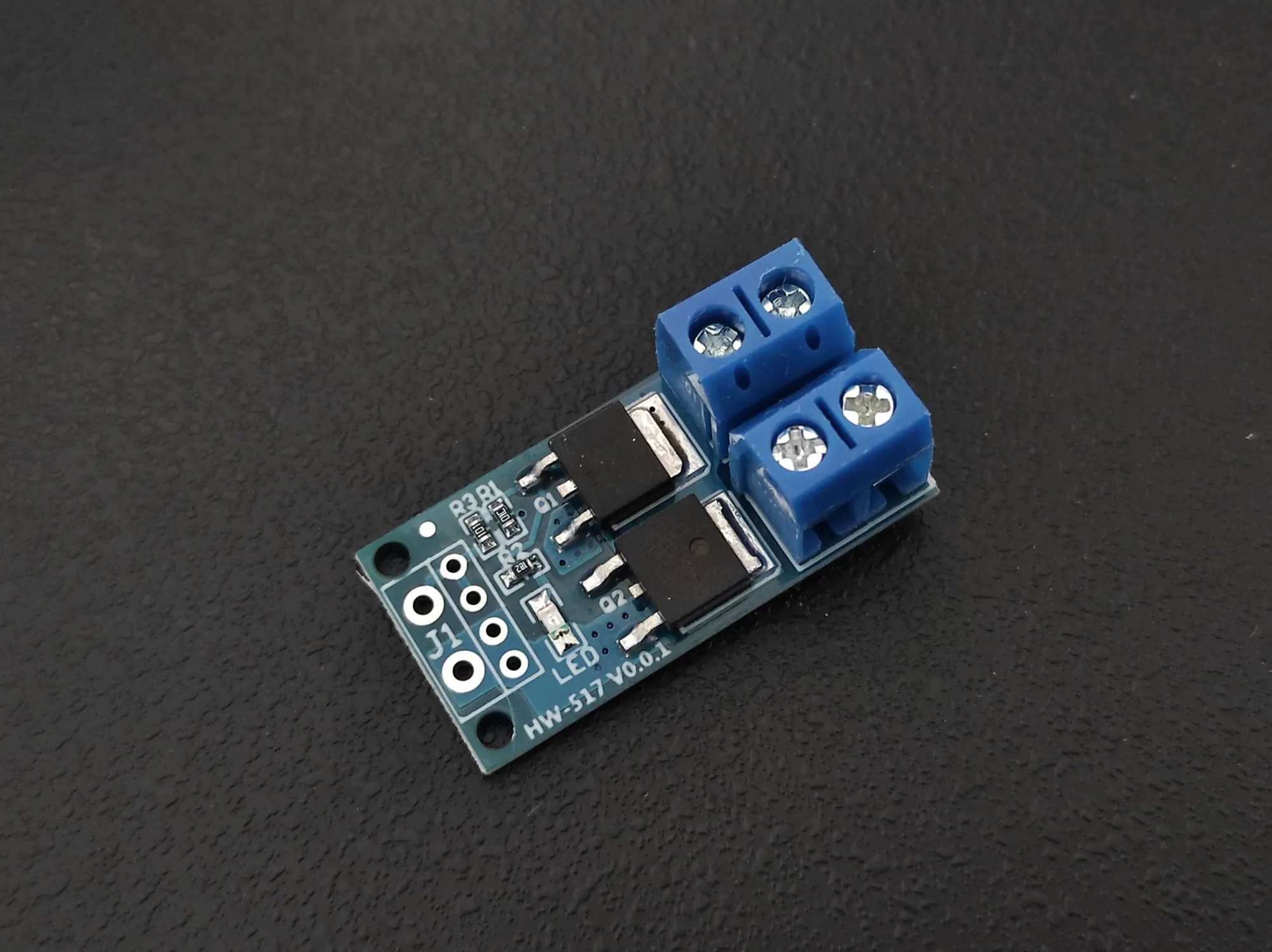
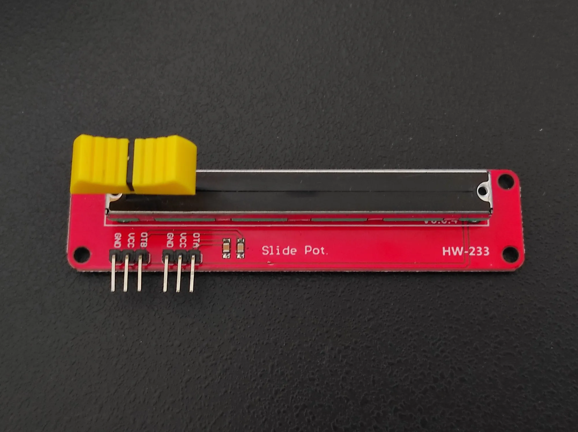
| Dimmer | Seeed XIAO RP2040, HW-517 dual-MOSFET module, HW-233 slide potentiometer, 12 V LED bulb |
| USB stick | RP2040 in a printed case, Adafruit CircuitPython HID |
| Laser | 650 nm 5 mW module in a Blender-modelled printed body |
Short hardware builds from 2024 and 2025. The largest is a 16×16 addressable LED panel running fire and ball-physics animations I wrote in C++, which later became a lamp controlled from a phone browser. Around it: a light pen, a 12 V dimmer, an RP2040 USB keyboard stick, and printed cases for a laser and a Linux single-board computer.
A light pen and a laser, 2024
The pen, from February 2024, is fairy-light LED wire, a small Li-ion cell and a USB charging module inside a transparent ballpoint; a side button cycles the modes and clipping it into a pocket turns it off.
The laser is a 650 nm 5 mW module, a cell, a rocker switch and a USB-C socket in a body I modelled in Blender around the module and printed in August 2024. On a phone set to a long exposure, the beam writes in light.
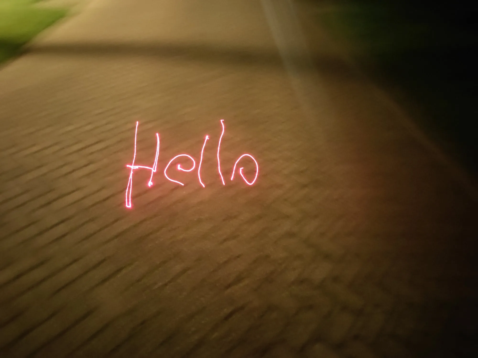
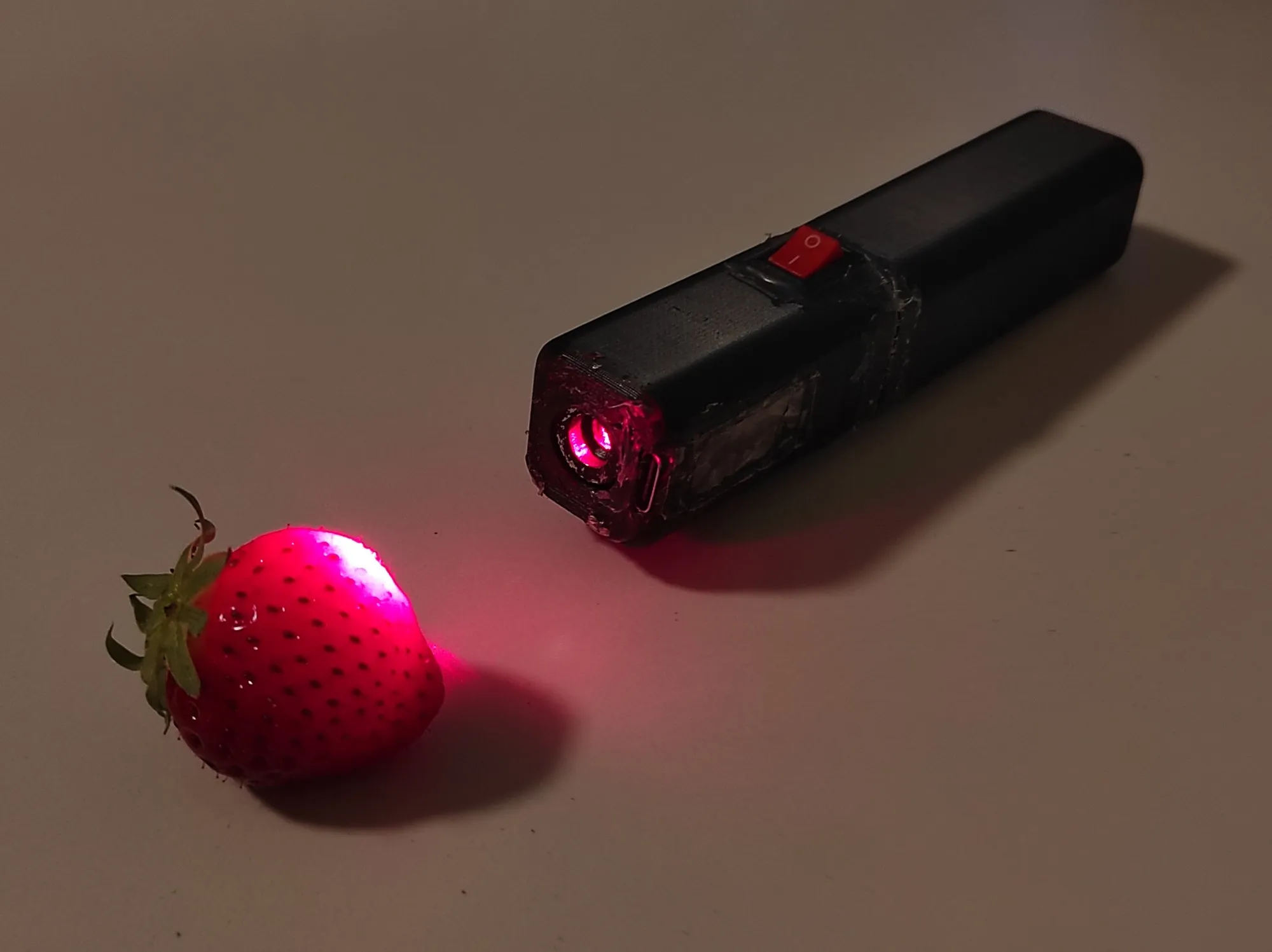
The laser in my 2025 build video, from 1:49
A 16×16 LED panel, then a lamp
The panel is a flexible 16×16 grid of WS2812 LEDs on one data line, driven from an Arduino-compatible board. The 256 LEDs form one chain laid in a zig-zag: it runs along one strip and comes back along the next, so LED 16 sits beside LED 15, not beside LED 0. Every sketch goes through one mapping function that flips the Y axis and reverses every second strip, and after that the animations work in plain (x, y) coordinates.
There are two fire effects. One is a port of a widely shared mask-based matrix fire to the Adafruit NeoPixel library, with its own HSV to RGB conversion: a random row of heat enters at the bottom, the rows shift up, each frame blends between two steps and a 16×16 mask subtracts brightness so the flame tapers. The other is my own shorter version: random heat fed in along one edge, shifted across the panel every 50 ms, and mapped from black through red and yellow to white. On 7 October 2024 the panel was bent into a tube inside a frosted plastic container, the first version of the lamp.
On top of the same mapping I wrote a ball simulation in C++. Each ball has a floating-point position, a speed and a heading in degrees, and moves by sine and cosine every 20 ms frame. A switch per axis decides whether a ball bounces off that edge, with a few degrees of random scatter, or wraps round to the opposite side.
In January 2025 I printed a cylinder that holds the panel and serves as the diffuser, and moved the control to an ESP32-C3 SuperMini on the back. It runs the animation and serves a control page over Wi-Fi with four buttons: Brighter, Dimmer, Max Brightness and Turn Off. No app, no cloud account.
The lamp in the build video, from 2:47
A touchscreen, a USB stick and a Linux board case
In November 2024 I ran touchscreen examples on the Cheap Yellow Display, an ESP32 board with a 2.8-inch touchscreen on the same ILI9341 panel controller as the sensor display.
The USB stick is an RP2040 board in a case I modelled in Blender and printed in December 2024, with a cap, a lanyard loop, two programmable buttons and a mode switch. Plugged in, the board enumerates as a USB keyboard and mouse and runs a stored script, as a USB Rubber Ducky does; mine moved the mouse pointer at random or opened a Rickroll. The switch keeps it inert until it is armed. The HID stack is Adafruit’s CircuitPython HID library with a keyboard layout generated by Neradoc’s CircuitPython Keyboard Layouts.
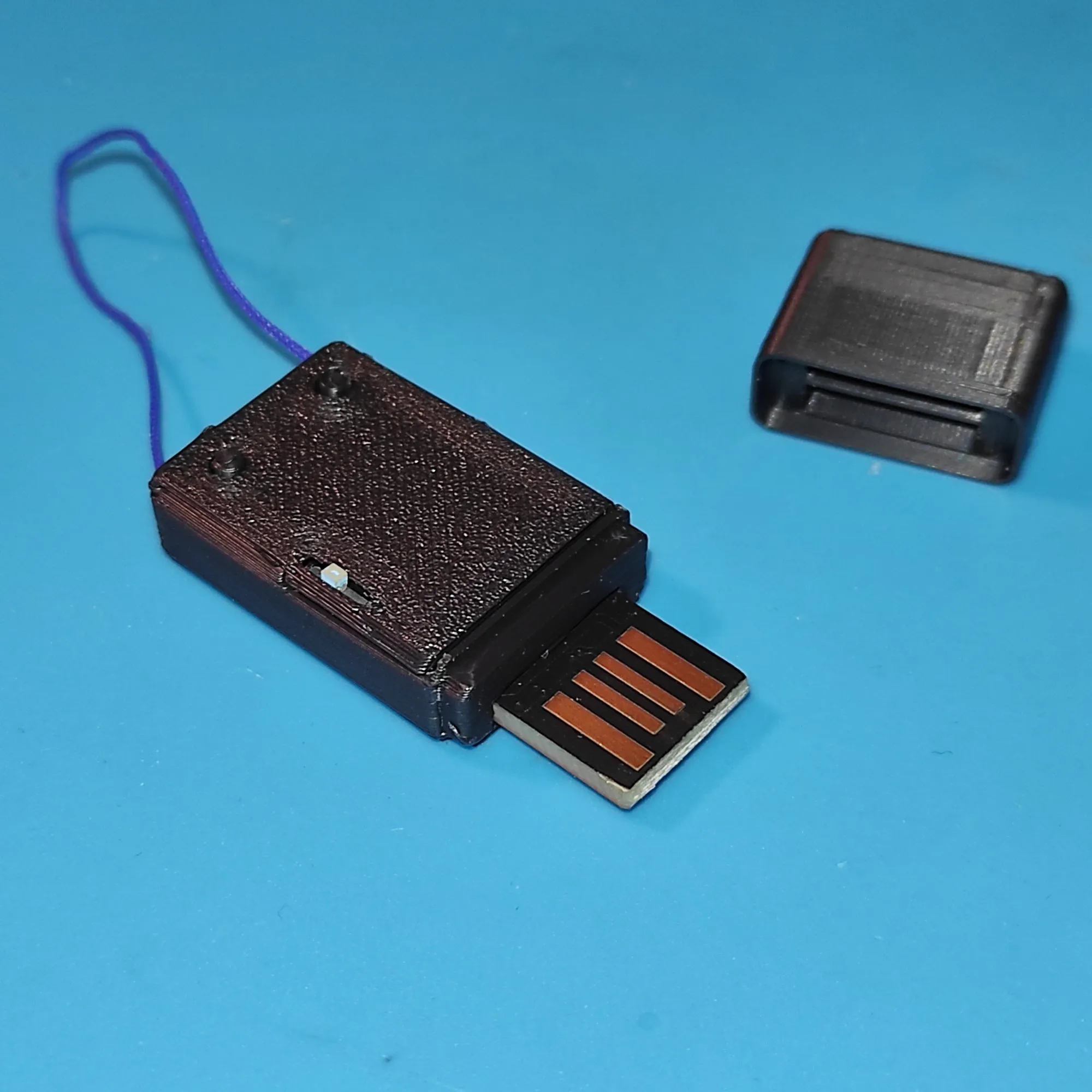
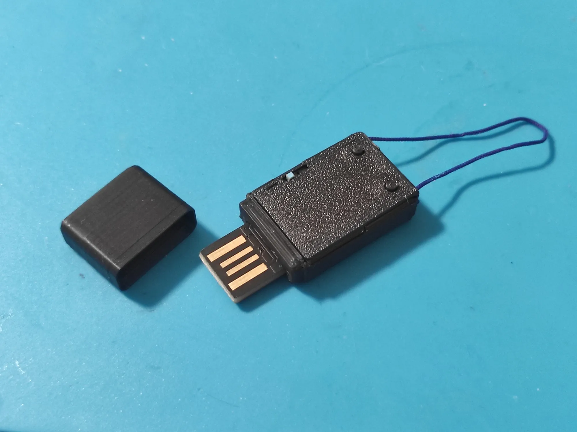
The USB stick in the build video, from 3:15
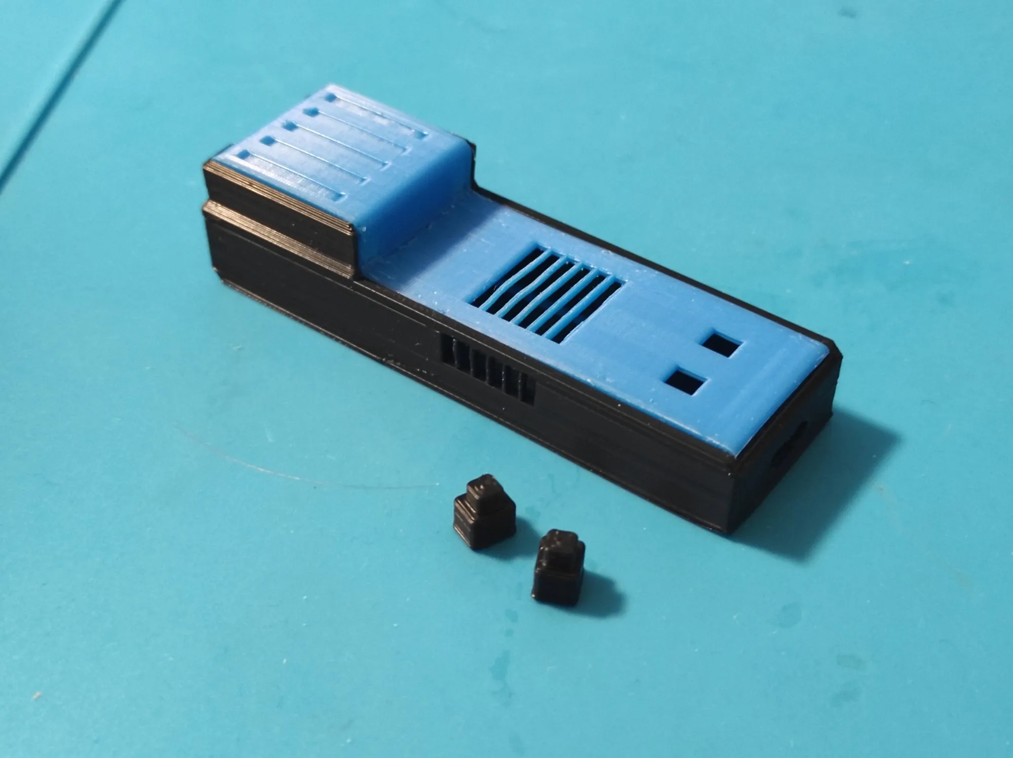
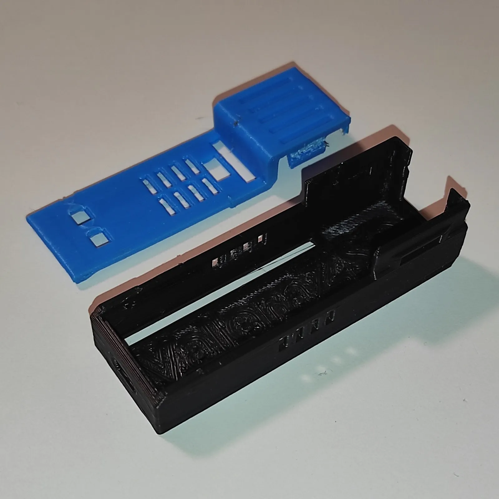
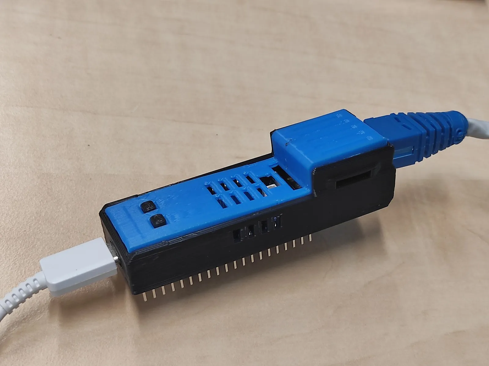
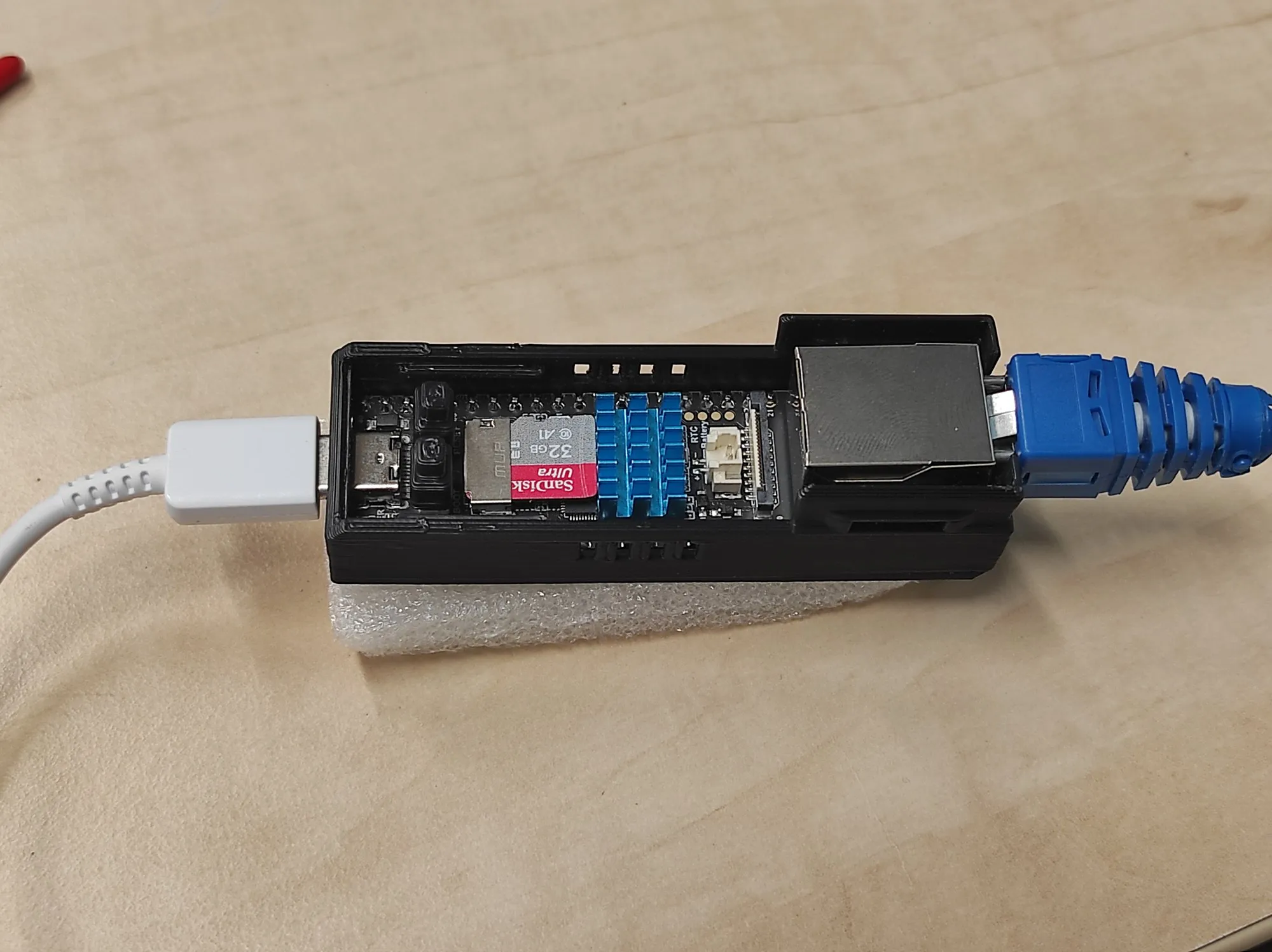
The Luckfox Pico Pro/Max is a small Linux board with an Ethernet port. Its case is two printed parts, a black body and a blue lid, with openings for USB-C, the microSD card and the Ethernet socket, vent slots and printed caps for its two buttons. I modelled it in Blender around a model of the board and printed two versions, in December 2024 and January 2025.
Switching 12 V from a 3.3 V pin
The dimmer, built in May 2025, switches a 12 V bulb from one 3.3 V output pin of a Seeed XIAO RP2040, through an HW-517 dual-MOSFET module. The XIAO reads an HW-233 slide potentiometer on an analogue input, turns the slider position into a PWM duty cycle and feeds it to the module’s input, and the MOSFETs switch the 12 V side at that duty cycle.